Engineered Carbon Fiber, Tailored to Your Build
From raw material selection to structural engineering — every JC AUTOCARBON component can be customized for performance, fitment, and visual impact. Five dimensions, top to bottom.
01 Material Selection — Wet & Dry Carbon Fiber
Two proven manufacturing routes, each optimized for a different balance of cost, weight, and performance. See the full dry vs. wet carbon comparison >>

Wet Carbon Fiber
Best for exterior upgrades — front lips, side skirts, canards
Manufacturing Process: Carbon fiber fabric combined with resin, formed through vacuum infusion or composite molding, followed by polishing, painting and clear-coat protection.
- Clear carbon weave appearance
- High-gloss visual effect
- Suitable for street modification projects
- Better cost-performance balance
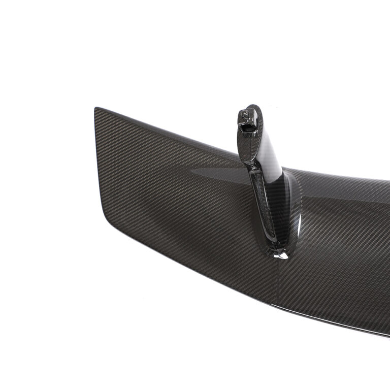
Dry Carbon Fiber
Best for lightweight & high-strength, track-grade performance
Manufacturing Process: Prepreg carbon fiber formed under controlled temperature, pressure and curing time to achieve precise fiber orientation and resin content.
- Lower weight
- Higher strength consistency
- Better stiffness control
- For performance vehicles & premium projects
02 Weave Pattern — Twill, Plain, Forged & Hybrid
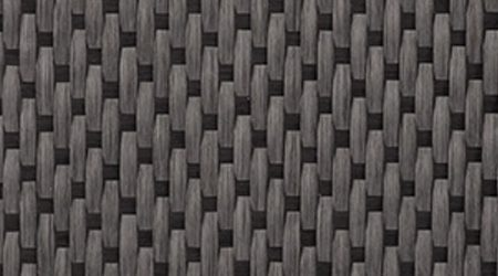
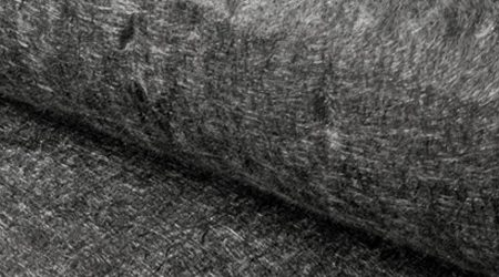
JC AUTOCARBON utilizes premium carbon fiber materials sourced from leading suppliers such as Toray, combined with advanced weaving technologies to produce high-quality fabrics in multiple grades (3K, 6K, 12K, unidirectional, and bidirectional). Each material undergoes rigorous tensile, thermal, chemical, and mechanical testing — ensuring consistency, reliability, and superior performance from raw material to final product.
 3K Twill
 3K Plain
 6K Twill
 6K Plain
 12K Twill
 12K Plain
 Satin Weave
 Non-woven
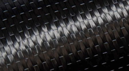 Unidirectional
 Bidirectional
2×2 Twill Weave
The most popular weave pattern in the automotive aftermarket. Characterized by its diagonal parallel rib pattern, it offers excellent drapability over complex curved automotive surfaces.
Visual Style: Deep, dynamic 3D reflection that accentuates the vehicle’s body lines.
Best For: Large exterior aero parts, including front hoods, rear diffusers, and side skirts.
1×1 Plain Weave
A tight, checkerboard pattern woven in a simple over-under structure. It offers a highly stable grid look with high structural uniformity.
Visual Style: Subtle, neat, and highly technical appearance — often preferred by European OEM manufacturers.
Best For: Mirror covers, interior dash trims, and steering wheel accents requiring extreme dimensional stability.
Forged Carbon
Formed by compressing chopped carbon fibers with resin under immense pressure. Because the fibers are randomly oriented, every single piece we manufacture is entirely unique.
Visual Style: A luxurious, multi-layered marble-like texture with metallic depth.
Best For: Premium bespoke projects, custom engine covers, wheel center caps, and high-end interior trims.
Hybrid Weave
Custom weave variations engineered to break the mold — specialized loom setups produce unique structures such as Herringbone (V-weave), honeycomb, or custom checkerboard weaves.
Visual Style: Highly exclusive, technical look that immediately differentiates your brand’s products.
Best For: Premium signature aero packages and custom engine covers.
Kevlar / Aramid Mix
Premium carbon fiber woven with high-tenacity DuPont™ Kevlar® (Aramid) fibers, introducing structural impact resistance combined with striking visual customization.
Visual Style: Seamless color integration (Red/Black, Blue/Black, Gold/Black) matching OEM paint or brand identities.
Best For: High-wear, impact-prone areas like front splitters, under-trays, and motorcycle fairings.
03 Surface Finish — Matte, Gloss & Clear-Coat
A full range of surface finishes with precise control over reflectivity and final appearance. JC AUTOCARBON’s automotive-grade, dust-free spray facility combines multi-layer manual polishing to ensure mirror-like smoothness that withstands harsh weather, UV radiation, and high-speed road debris.

High-Gloss Clear Coat
The industry standard for showcasing intricate carbon weaves. We apply 3–4 layers of high-solid automotive clear coat, followed by rigorous multi-stage hand polishing.
Visual Effect: A wet-look, deep 3D gloss surface that accentuates the carbon pattern under any lighting.
Best For: Exterior aerodynamics (front lips, rear diffusers, spoilers) and high-visibility body panels.
Matte / Satin Finish
A sophisticated finish offering a sleek, satin-smooth texture. It eliminates harsh reflections while maintaining the tactile, high-tech essence of raw carbon fiber.
Visual Effect: A non-glare, understated stealth look. Highly resistant to visible fingerprints and dust.
Best For: Interior dash trims, steering wheel bezels, engine covers, and vehicles with satin/matte wraps.
Advanced UV-Protection Coating
Anti-yellowing & weather-resistant armor. Our coating formula is infused with advanced UV inhibitors that block harmful ultraviolet radiation.
Best For: Every exterior component exposed to long-term sunlight and extreme climates.
04 Color Effect — Classic Black & Kevlar Blends
Carbon fiber is no longer limited to classic black. Through in-house dual-fiber weaving with genuine Kevlar® and specialized UV-stabilized chromatic clear coats, we offer rich, deep, and stable color infusions that align with your brand identity or vehicle paint codes — engineered to withstand extreme solar radiation without fading or yellowing. How colored carbon fiber is made >>

Gloss Black
Standard black carbon with a high-gloss, mirror-polished clear coat.
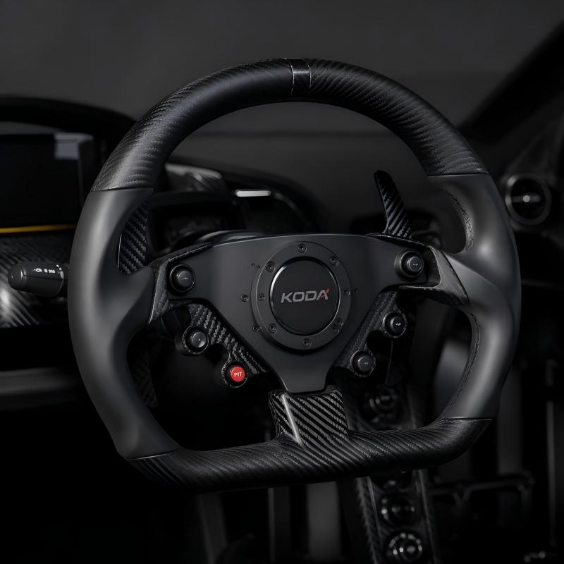
Matte Black
Standard black carbon with a non-reflective, satin/matte clear coat.
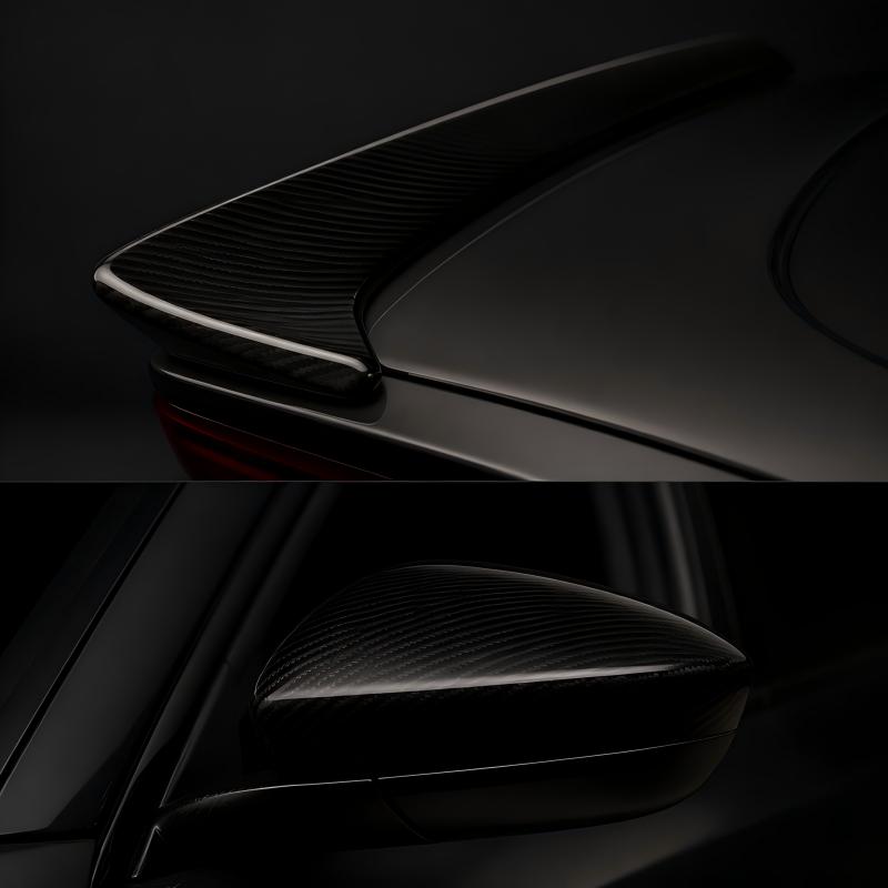
Smoked Black
Black carbon finished with a semi-transparent smoked black tint coat.
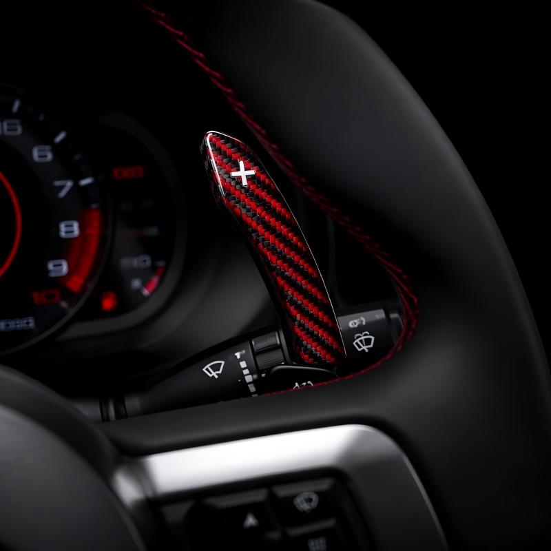
Red & Black Hybrid
1:1 interlaced weave of black carbon and red aramid (Kevlar) fibers.

Blue & Black Hybrid
1:1 interlaced weave of black carbon and blue aramid (Kevlar) fibers.

Yellow & Black Hybrid
1:1 interlaced weave of black carbon and yellow aramid (Kevlar) fibers.

Texalium Silver
Glass fiber weave with micron-level aluminum coating — metallic silver finish.

Candy Green Tint
Black carbon base topped with semi-transparent green clear coat.

Candy Red Tint
Black carbon base topped with semi-transparent red clear coat.
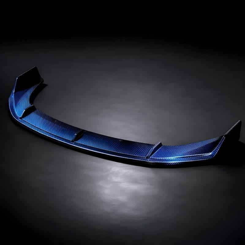
Candy Blue Tint
Black carbon base topped with semi-transparent blue clear coat.
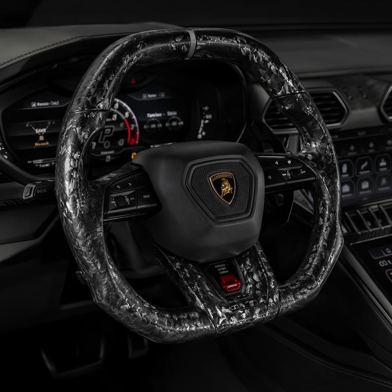
Standard Forged Carbon
Chopped carbon strands compressed under high pressure — irregular marble pattern.

Gold Flake Forged
Chopped carbon mixed with gold leaf flakes, molded under high pressure.

Silver Flake Forged
Chopped carbon mixed with silver/aluminum flakes, molded under high pressure.

Metallic Flake Forged
Chopped carbon mixed with metallic colored pigment flakes, molded under high pressure.
05 Structure & Installation — Engineering-Validated Fitment
Select structural and mounting solutions based on part size, transport needs, replacement requirements and load-bearing conditions. From mounting strategy to fitment validation, we develop carbon fiber parts that fit precisely, install securely, and remain stable in real-world use.
One-Piece Structure Design
One-piece molding provides a cleaner appearance with no visible joint seams and higher overall rigidity.
Multi-Piece Structure Design
Multi-piece construction improves transportation efficiency, reduces replacement cost, and allows flexible assembly for larger body kit systems.
OEM Replacement Installation
For replacement parts such as hoods and fenders, we focus on OEM mounting points, hinge areas, lock positions, panel gaps, and direct-fit installation accuracy.
Add-On Installation
For add-on exterior parts, we design the installation method using 3M adhesive, clips, bolts, or combined fixing solutions according to part shape and vehicle surface.
Bracket Installation
For large aerodynamic components, bracket-mounted installation distributes load and maintains stability under high-speed driving. Brackets and fasteners can be developed as part of the complete solution.
Metal Mounting Inserts
Metal mounting inserts can be embedded during the carbon fiber molding process to improve load distribution, installation strength, and long-term stability.
- Embedded mounting points
- Stronger load distribution
- Reduced loosening risk
- Suitable for intake systems and structural parts
- Better long-term assembly stability
Choose the Right Development Path for Your Project
Different carbon fiber projects need different development logic. Choose the path that best matches your project type — exterior styling, aerodynamic performance, or structural composite parts.
Exterior Body Kit
Styling-driven exterior parts that follow body lines, install cleanly and repeat in batch production.
CFD Aero Parts
Functional aerodynamic components developed with CFD simulation, prototype validation and real track testing.
Structural Carbon Parts
CAD-driven structural composite parts with controlled layup, embedded inserts and OEM-level repeatability.
Requirement Alignment
Feasibility & Engineering Plan
Process & Tooling Validation
Final Manufacturing & Quality Control
* Early design and confirmation time are not included.
P1 Exterior Body Kit Development
For exterior styling parts, good appearance is only the starting point. A successful body kit must follow the vehicle’s body lines, install cleanly, protect the mounting structure, and remain repeatable in batch production.
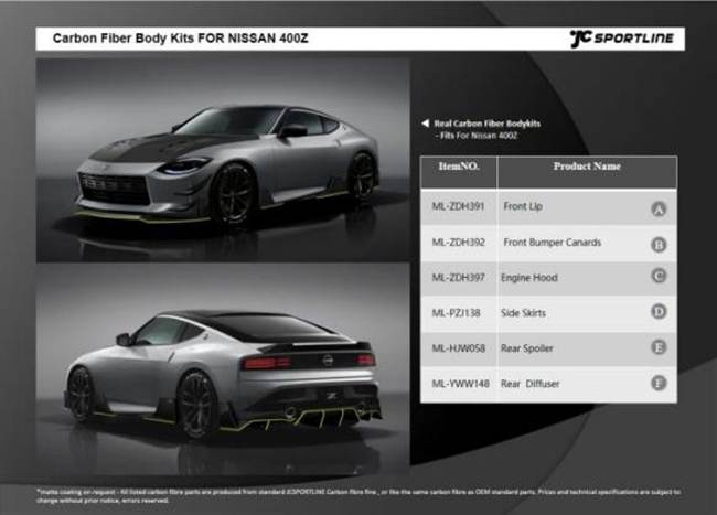
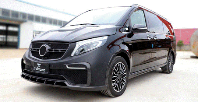
JC AUTOCARBON develops carbon fiber front lips, side skirts, diffusers, spoilers, hoods, fenders and full body kits with fitment and manufacturability checked from the first design stage.


Body Kit Development Process — 10 Steps
3D Scanning Data
Original full-vehicle or local 3D scanning; collect mounting points and body-line data. Overseas teams can provide on-site scanning in Europe / the United States.
Concept Sketch
Create 2–3 styling direction sketches based on the customer’s positioning and design style.
Render
Generate installation renderings based on the original vehicle model. These renderings are for visual confirmation only and do not mean tooling has started.
3D Reverse Engineering
Build an accurate base vehicle model by reverse engineering the scan data.
3D Design Modeling
Design front lip, side skirt, rear lip, wing/spoiler and other body kit structures; process mounting points, part-splitting plan and DFM review.
Sample Production
Produce the first sample, complete surface treatment and clear coat, and issue the first-article inspection report.
Testing & Adjustment
Verify fitment, gaps, strength and appearance through real-vehicle trial installation; fine-tune the mold when necessary.
Customer Approval
Submit sample photos, videos and inspection report; lock the mass-production standard after customer approval.
Mass Production
Start batch production according to the locked standard; inspect each piece before shipment.
Engineering Checks
- Body line matching
- Gap and edge alignment
- Mounting point strength
- Split-line and transport logic
- Mold demolding feasibility
- Carbon weave direction
- Gloss / matte surface quality
- Batch fitment repeatability
Recommended Materials / Processes
P2 CFD Aero Parts Development
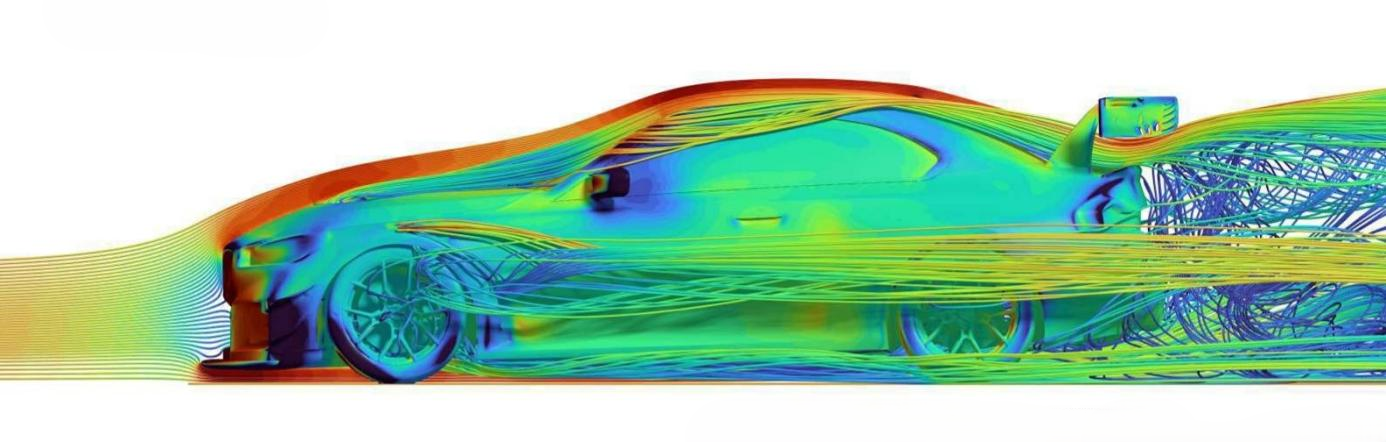
Aerodynamic parts must do more than look aggressive. A splitter, diffuser, wing or canard should control airflow, improve stability, reduce unwanted turbulence and support the vehicle’s performance goal.
JC AUTOCARBON uses CFD-driven development logic, prototype validation and real-world testing to develop functional carbon fiber aero parts for track-focused and performance applications.

CFD Aero Parts Development Process — 11 Steps
Customer Intent
Define product goals, target vehicle, usage scenario and expected performance.
Feasibility Review
Evaluate structure space, installation limits, cost, material and development timeline.
Aero Concept Development
Define the airflow function: downforce, cooling, drag reduction or flow management.
Render Preview
Output design renderings and confirm styling coordination with the complete vehicle.
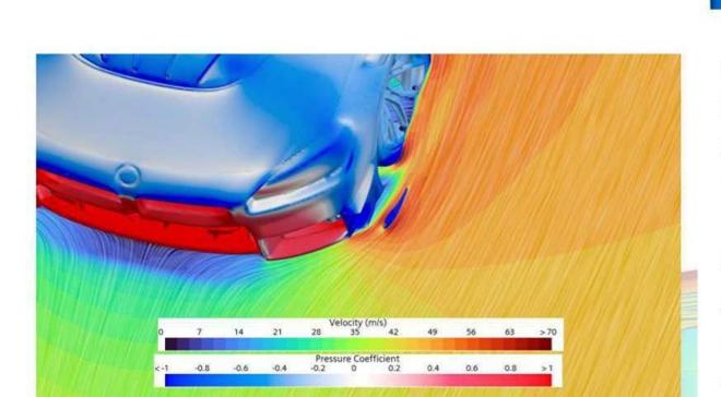
CFD Simulation
Use RANS baseline simulation to evaluate airflow path, pressure distribution, downforce and drag; use hybrid LES high-precision validation for key conditions.
Design Optimization
Iterate shape, angle, edges and guide structures according to CFD results until the target is met.
Mold Development
Plan the mold solution and complete CNC machining.
Sample Production
Produce the first dry-carbon sample and prepare for vehicle installation validation and functional testing.
Real Track Testing
Verify aerodynamic performance, installation stability and real-world effect on real roads or track.
Final Validation
Make final corrections according to test results and confirm the mass-production version.
Mass Production
Start formal mass production and pre-shipment inspection.
Engineering Checks
- Airflow path and pressure distribution
- Front / rear aero balance
- Drag and downforce relationship
- Wheel-arch airflow management
- Wing profile and angle range
- Diffuser exit flow
- Cooling vent logic
- Mounting rigidity under high-speed load
- Dry carbon layup and stiffness design
Recommended Materials / Processes
Deliverables
P3 Structural Carbon Parts Development
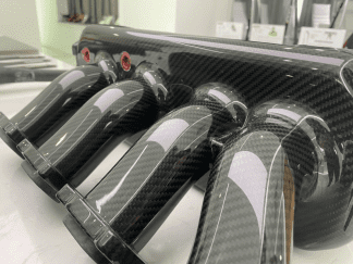
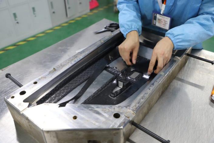
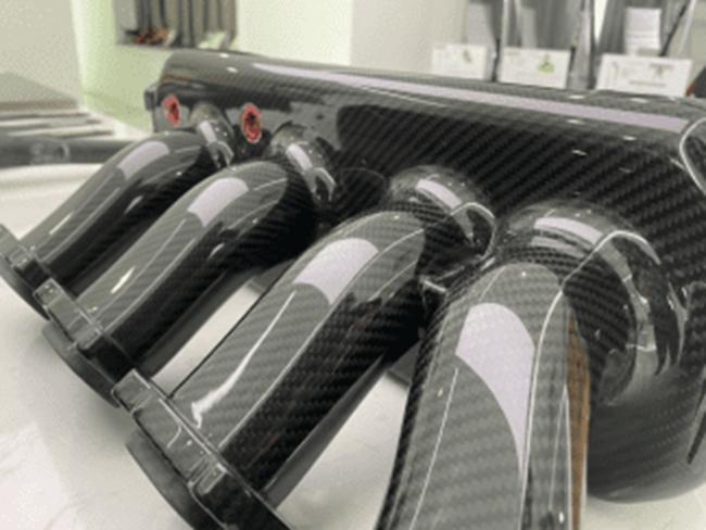
Structural carbon fiber parts require more than a cosmetic carbon surface. They need controlled layup, stable tooling, accurate interfaces, embedded mounting structures, heat or pressure resistance and reliable assembly.
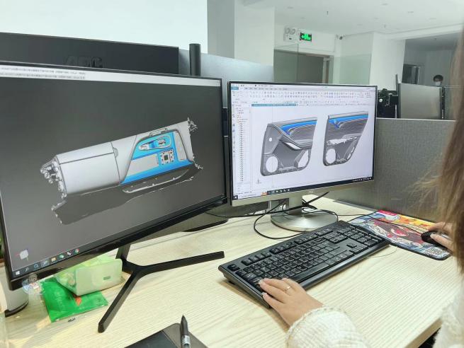
JC AUTOCARBON supports CAD-driven and sample-driven structural composite projects including intake systems, interior structures, brackets, embedded parts and performance components.
Engineering Checks
- CAD data completeness
- Assembly interface accuracy
- Embedded metal insert design
- Fiber layup direction
- Resin and curing method
- Bonding or one-piece forming feasibility
- Heat / pressure / impact resistance
- Dimensional control under production conditions
- Batch repeatability
Recommended Materials / Processes
What We Do — From Concept to Production
You bring the idea. We help shape it into something that can actually be built — checking styling, fitment, composite behavior, mold logic and production consistency before expensive tooling decisions are made.
Concept & Design
You bring the sketch, CAD file, sample part or reference photos. We define styling direction, vehicle fitment, mounting strategy and production feasibility.
Engineering & DFM
Carbon fiber does not behave like metal. We plan layup direction, resin system, reinforcement, parting lines and demolding logic before tooling starts.
Tooling & Prototype
Molds and first samples are built for real fitment checks, surface review, installation testing and structural validation.
Production & Scale
Approved parts move into batch production with controlled QC for surface finish, dimensional accuracy, installation fitment and batch consistency.
Why Carbon Fiber Development Projects Go Wrong
Good renders are not enough. Carbon fiber development fails when design decisions are separated from tooling, installation, material behavior and repeatable production.
Good Looks, Bad Fitment
A render can look perfect, but if surface data is inaccurate or mounting points are weak, the part will not install cleanly.
Design Without Tooling Logic
If mold structure, parting lines and demolding direction are not planned early, production becomes expensive, unstable and hard to repeat.
Prototype Works, Mass Production Fails
Handmade samples can look great. The real question is whether the same part can be produced 100 times with the same surface, fitment and structure.
No Validation Before Delivery
Without fitment checks, dimensional control, UV testing and temperature cycling, problems appear after customers already receive the part.
Projects / Case Studies
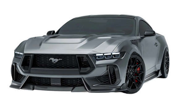
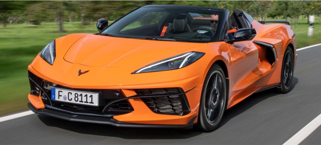

Why Brands Choose JC AUTOCARBON for Custom Carbon Fiber Development
A custom carbon fiber project is not only about making a good-looking part. It requires accurate vehicle data, composite engineering, tooling logic, fitment validation and stable batch production. JC AUTOCARBON connects these steps under one development workflow, so brands can reduce tooling mistakes, launch faster and scale with confidence.
In-House Development Workflow
Design, reverse engineering, DFM review, tooling, prototype validation and production are coordinated in one system instead of being separated across disconnected suppliers.
Composite Engineering First
We plan layup direction, resin system, reinforcement zones, embedded structures and curing methods according to the part’s function, not by guesswork.
Fitment Before Mass Production
Samples are checked on real vehicles or assemblies for gaps, mounting points, installation logic and structural performance before batch production begins.
Production-Ready Thinking
Every design is reviewed against mold structure, demolding direction, surface quality, repeatability, QC standards and future volume needs.
Get a free feasibility report before you start tooling
Send us your concept, sketch, CAD file, sample part or reference photos. Our engineering team will review your idea and send back a free feasibility report with material suggestions, structure advice and an estimated timeline.
Factory-Direct Carbon Fiber,
Built for You
Custom parts engineered and manufactured in-house — from one-off samples to bulk orders.
Free quote · No obligation · Takes about 1 minute
In a hurry? Chat on WhatsApp →
Working hours: Monday – Saturday, 9:00 – 18:00 (GMT+8)