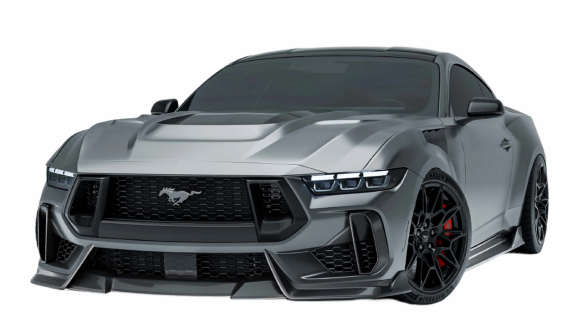
Carbon Fiber Intake Pipe System – Performance Vehicles
Project Overview
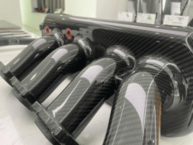
This project developed a carbon fiber intake pipe system for performance vehicles. Complex pipe shapes were produced as one-piece autoclave-cured parts with bonded joints and smooth inner walls. This reduces part count and mechanical fasteners, improves airflow, simplifies assembly, and keeps quality stable across batches.
Project Info
Project Name | Carbon Fiber Intake Pipe System – Performance Vehicles |
|---|---|
Project Timeline | Standard JC AUTOCARBON reference cycle: after design data is confirmed, most projects complete first samples in 45-58 days (CNC mold making 15-20 days, mold replication 20-25 days, sample production 15-20 days; early design and confirmation time not included). |
Order Quantity | 1,000 sets |
Client Type | Performance air intake brand |
Process Type | Prepreg autoclave one-piece molding + adhesive bonding |
Client Requirements
A performance air intake brand needed a carbon fiber intake pipe system that smooths airflow and improves engine response. The design had to cut part count and assembly steps, stay repeatable in batch production, and meet strict heat, pressure, and sealing requirements – proven by pressure testing and burst testing.

From customer data to structure and interface design
Scope of Customization
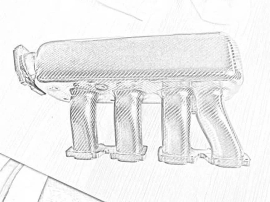
JC AUTOCARBON delivered prepreg autoclave curing, complex one-piece molding, adhesive bonding instead of mechanical fasteners, and a smooth inner wall design for the airflow path. Where needed, metal mounting inserts can be molded directly into the carbon layers, so loads spread more evenly and long-term loosening risk is lower.

Smooth inner wall of the one-piece intake pipe 
Clean flange and bore finish for stable airflow


Pain Point
Intake pipes have complex geometry. Traditional multi-piece designs with mechanical fasteners have many joints and an uneven inner wall, which creates turbulence and hurts engine response. More parts and fasteners also mean harder assembly, higher cost, and more variation between batches.
Solution
On the manufacturing side, JC AUTOCARBON used stable high-temperature autoclave curing, one-piece molding of complex shapes, and reliable structural bonding to keep the pipe body, interfaces, and bonded areas consistent. Digital cutting and layup control the wall thickness, and inner-surface measures reduce resin residue and bag marks inside the pipe.
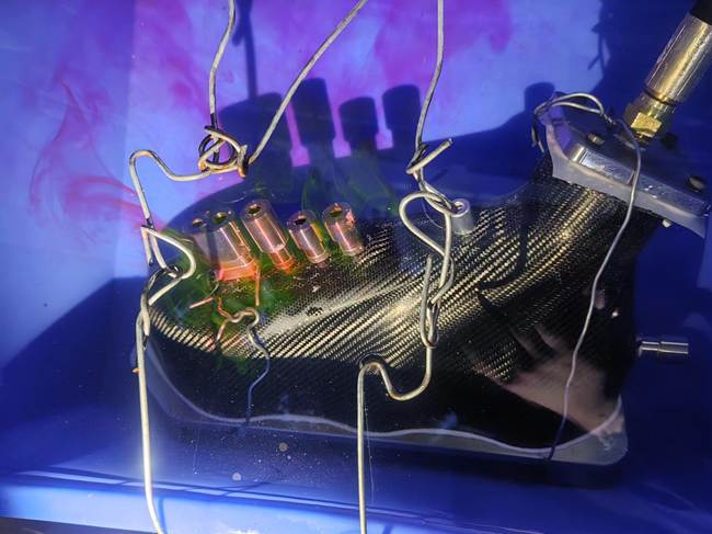
On the testing side, two levels of checks were set. The base requirement is 0.5 MPa pressure resistance, over 100 degrees C heat resistance, and good air tightness. Finished parts in this project were accepted at 120 degrees C and 0.7 MPa internal pressure with zero leakage and zero structural damage. Representative samples also passed destructive burst testing to prove the structural safety margin.
Underwater pressure and leak testing 
Air tightness test under internal pressure

Final Result
The project closed the full loop from structure design and manufacturing to test validation. Every set passes the required pressure and sealing checks, and sample parts passed burst testing, proving the safety margin of the pipe body, bonded areas, and reinforced interfaces. The smooth inner wall and one-piece design reduce joints and airflow disturbance, helping stable intake flow and engine response – while fewer parts and assembly steps improve batch consistency and delivery stability.
Other Projects / Case Studies
More +